Some variants of the CD4013 that people have been using seem to stall or at least go into an always on state if the gate signal is > 5v. This shows itself as the accent always being on, and the decay knob not adjusting the envelope.
You can solve this by attenuating your gate signal to ~5v, but if your gate trigger is sending > 5v signals and you want to have a permanent fix, then a small tweak to board pre version 1.6.3 allows the signal to be attenuated on board.
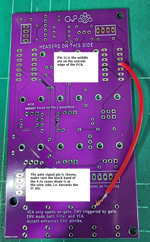
You will need a 4.7v Zener Diode – such as a 1N5230B (Mouser part : 78-1N5230B).
You need to cut the existing trace between the Gate Input jack signal pin and pin 11 of the CD4013. You can either cut this close to the gate jack itself, or close to the CD4013, the pictures below show the trace. Note that depending on your PCB version, the trace maybe like the board layout CAD picture below – or like the photos.
In all cases the pictures below show lime green marks where we’d recommend you cut the trace – note only one cut needs to be made, so pick the one you feel is easiest for you to cut. Make sure you only cut this one trace!
Then make your own trace basically, with the 1N5230B diode inline between the two points. The black band should be facing away from the Gate jack pin, towards to CD4013 as shown in the picture.