

TB-Valhalla – 303 Inspired Desktop
December 2023 – New firmware available…
August 2023 – DIY kits are available to order from synthesizer.nz and as pre-built systems built to order.
The TB-Valhalla combines the modules available in the TB- range of eurorack modules into a single stand-alone desktop synthesiser.
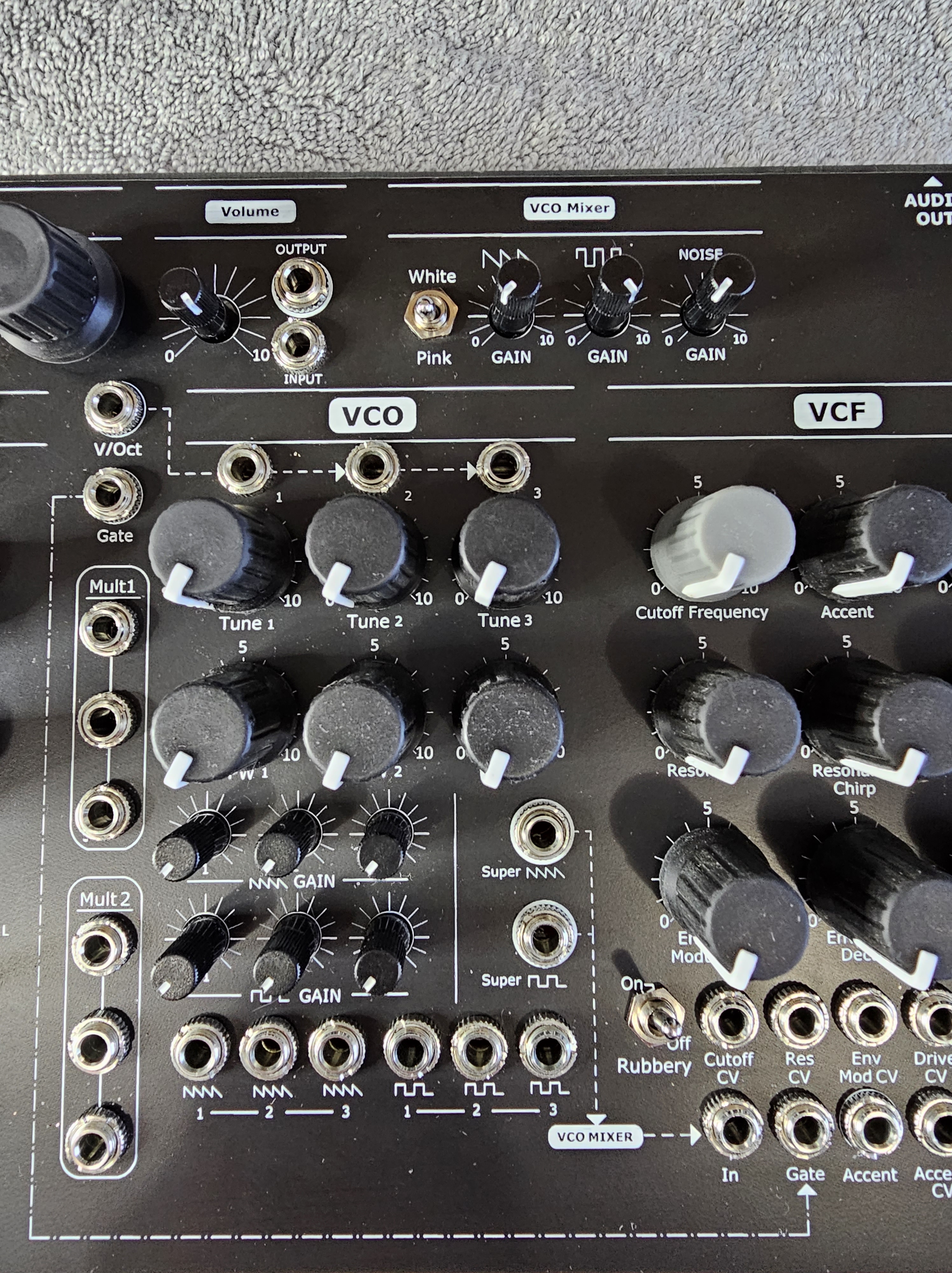
Not just another 303 clone, the TB-Valhalla gives you three tunable 303 oscillators, each with the usual features available in the TB-Super-O module. So six waveform outputs, (3 saw, 3 sqr), two Super waveforms and PW on the square. With volume control for all six of these waveforms you can craft sounds from the standard mono 303 through detuned 5ths into Super-saw territory and more.

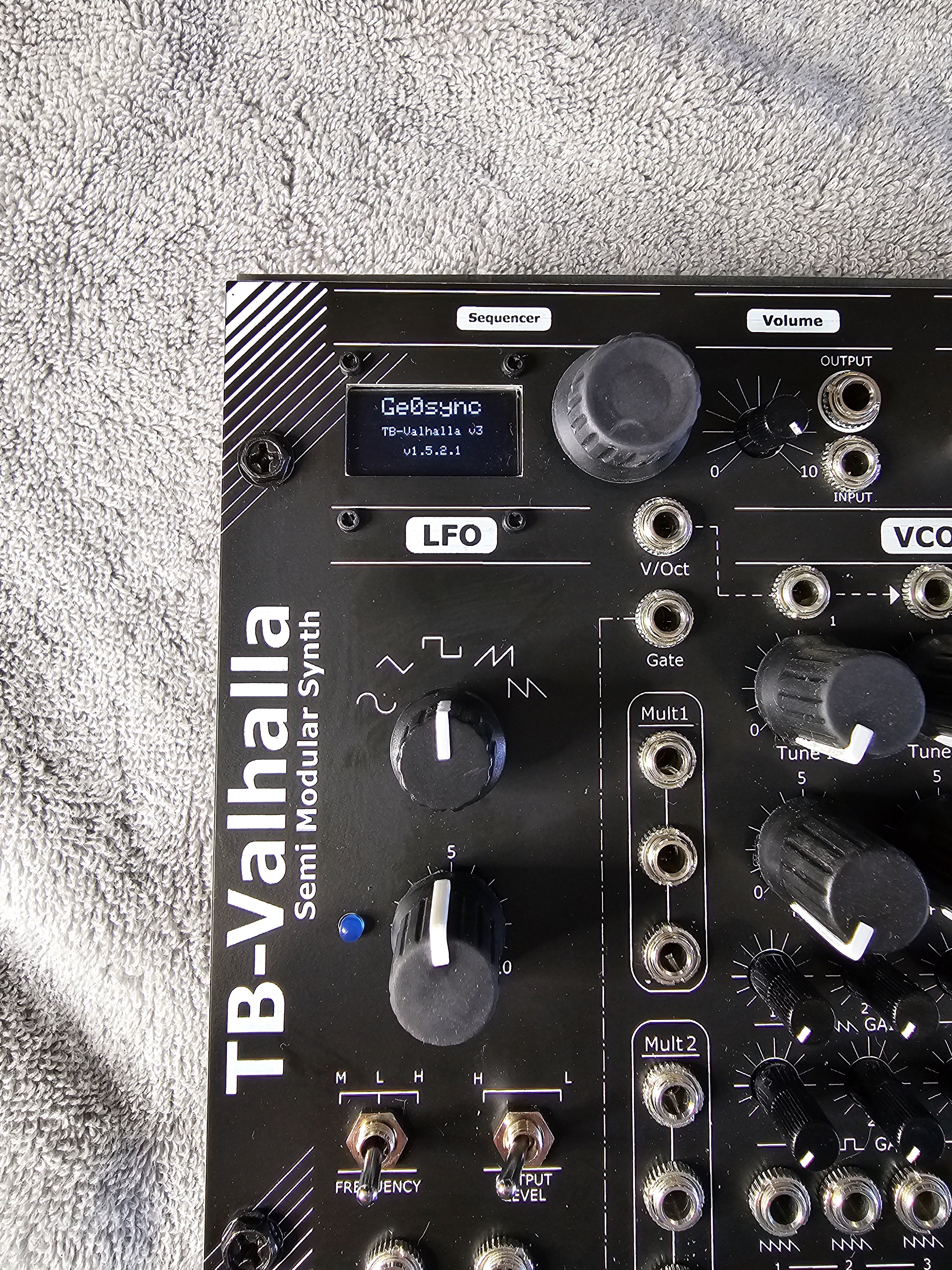
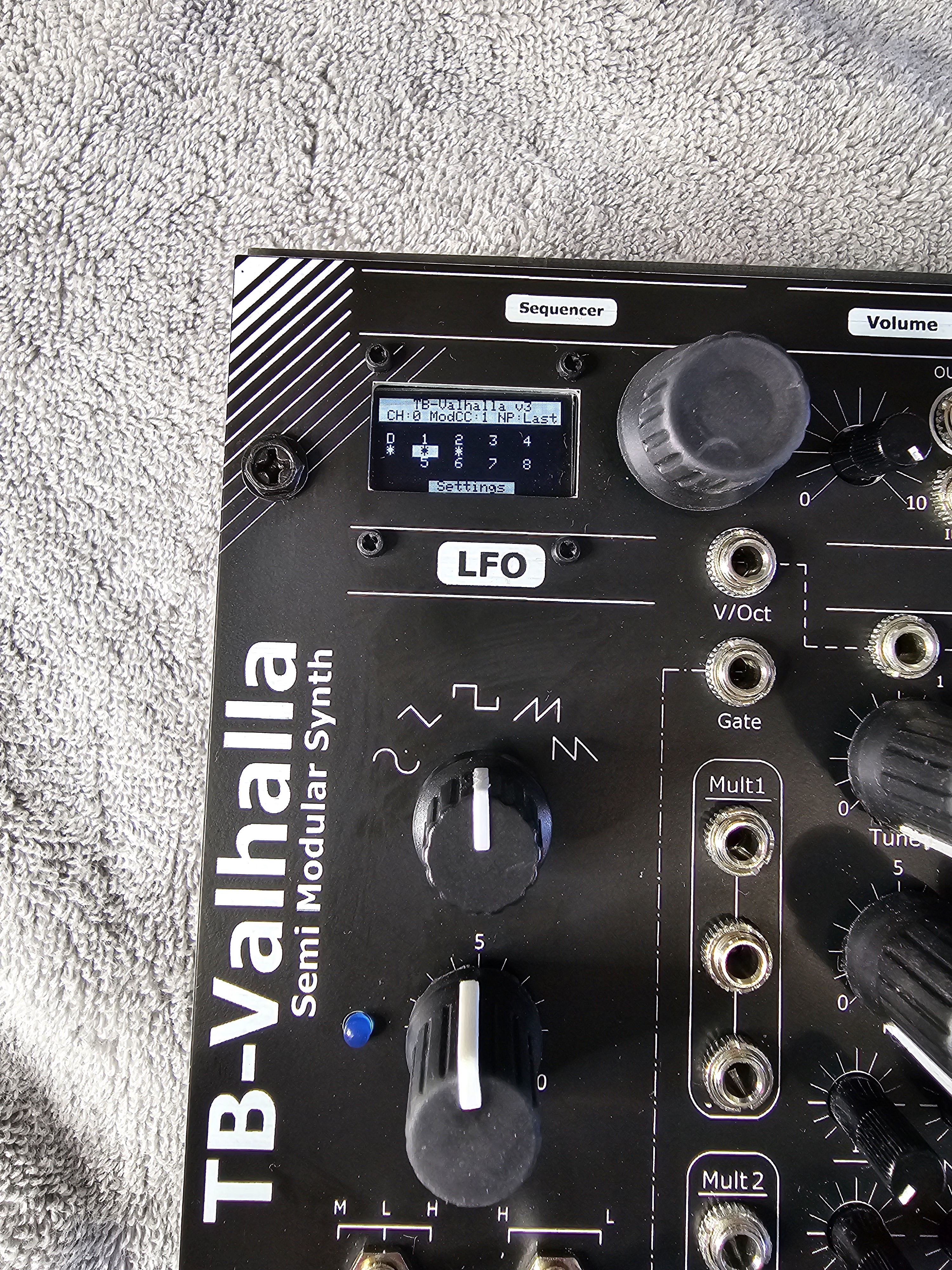
Built into the top left hand corner of the synth is the display for the 16 step, 8 pattern MIDI to CV sequencer module (TB-Seq) with built in menu system controllable by the encoder. The sequencer provides the usual 16 step TB style programming, with each step having the note, octave (1 to 5), accent and slide controls. Rests can be inserted and notes can span between 1 and 4 steps.
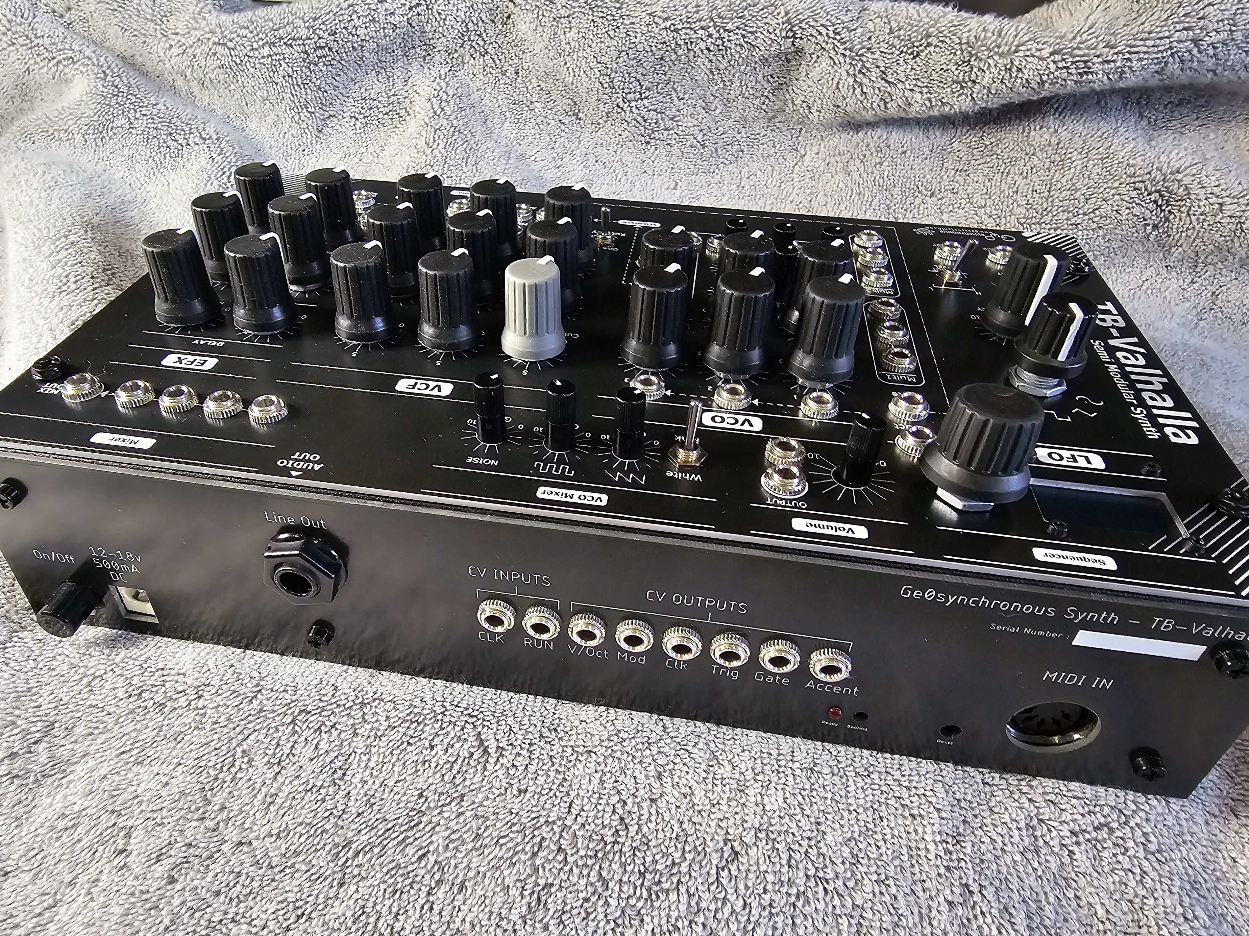
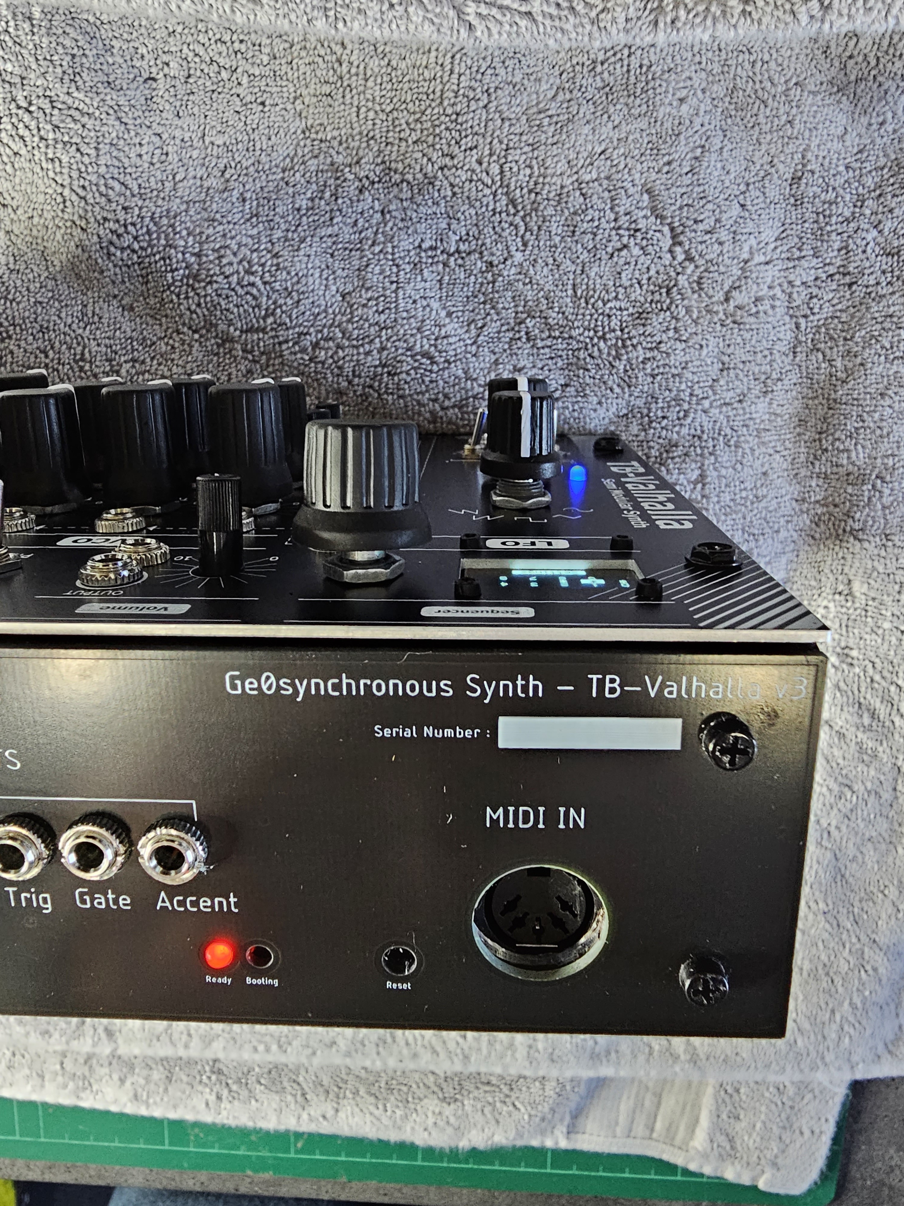
The sequencer itself responds to MIDI start/stop from the 5pin MIDI input on the rear panel, or can be triggered by a 5v RUN trigger and CV clock.
- CV Inputs : RUN/STOP, Clock, external V/Oct and Gate
- CV Outputs : From sequencer – V/Oct, Gate, Trigger, Accent
- CV Outputs : From MIDI – Mod, V/Oct, Clock

The clock in and out can be subdivded and are configurable via the menu or companion Ge0sync Sequence Editor application, available in the Downloads section for Windows and Mac. For more details and usage information for the sequencer and app, see the Users Guide.

Across the rest of the top of the TB-Valhalla you will find the output section with volume control. The input here can be used to bypass the normal signal flow and send a different audio signal to the Euro strength output jack and line level 1/4″ TRS output on the rear.
As there are several VCO outputs, a mini VCO pre-filter mixer is next. This allows you to select to mix the Super-square and Super-sawtooth waveforms (with their own gain control) while adding either white or pink noise before sending the mixed audio on to the classic 303 resonant filter.
On the far right we finish off this section with a 4 input buffered mixer for audio or CV signals.


Speaking of the filter it is a new derivative of the best selling TB-EFA module. So everything you’d expect to find in a 303 filter – resonance, cutoff, decay and accent. The TB-Valhalla maintains the additional drive, width and chirp controls, and most settings can be CV controlled.
New to this filter instance is the VCA decay control allowing short fast plucky sounds compared to the default longer tones. In addition a new “rubbery” toggle switch provides an extra smoothing on the envelope to further sculpt your tone.
With the noise inputs, when isolated by the mini-mixer, the filter can be used to create percussion tones, the pink noise in particular sits nicely with some filter resonance. Try crazy chrip and it becomes zappy!
The gate and accent into the filter are internally wired from the sequencer outputs, so instant 303 like control from the start!
Modulation wise you can use the LFO to modulate any of the CV inputs in the VCF section.

Rounding off the module we have included the TB-FX module. Providing some short period delay, from flanger to repeating notes giving you classic 303 filter sweeping delays. But no self-respecting acid bassline is complete without some distortion. While the filter provides a pre-filter drive level, add in some overdrive on the output for harsh and knarly tones.
The FX are not hard-wired, so patch the filter output to one or both effects in series and send the resulting output to the main volume section.
On the left hand side, between the LFO and VCO we have additional CV inputs to control the note (V/Oct) and gate to override the sequencer or MIDI inputs – these will send the signal to the VCO and VCF respectively. Below that you have two passive multiples for duplicating signals.
Hardwired for instant sound.
The synth is semi-modular, that is if you just plug in a MIDI keyboard or CV and gate signal you will get a fixed path signal from the outputs.
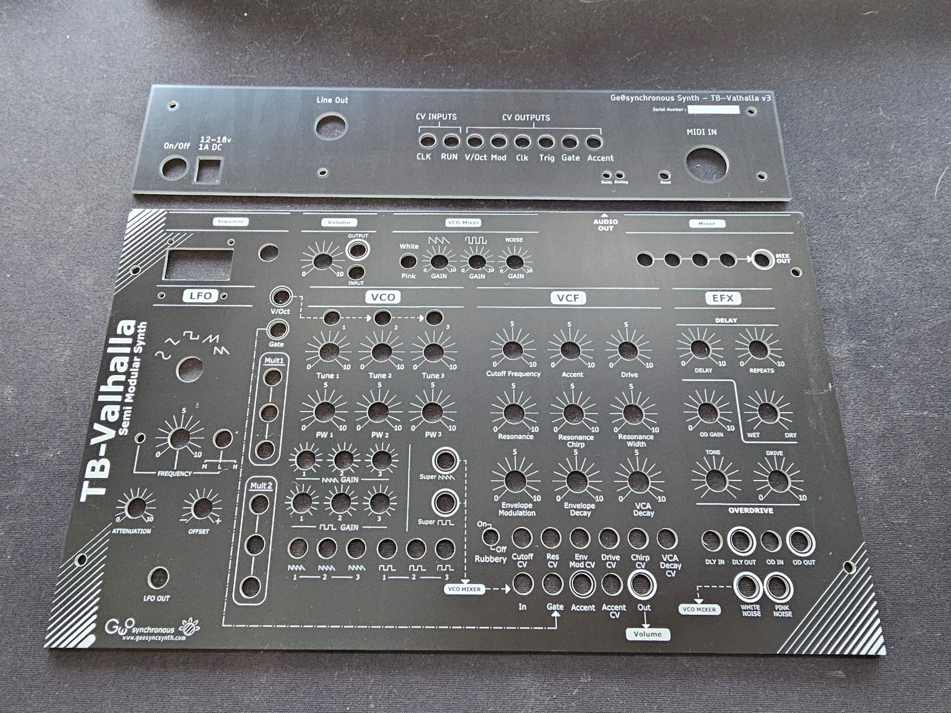
The internal signal flow is shown for reference on the front panel.
All hard wired paths make use of the switching pin on the jacks, so as soon as you plug in a cable the default signal path is cut and you are now building your own custom patch.
The default signal flows are :
Sequencer
- Note -> V/Oct output and V/Oct VCO1 input (VCO1 is normaled to VCO2) (VCO2 is normaled to VCO3)
- Gate -> Gate output and Gate -> VCF Gate
- Accent -> Accent output and VCF Accent
MIDI
- Note -> V/Oct output and V/Oct (as above)
- Note on/off -> Gate output and Gate -> VCF Gate
- Mod wheel (CC configurable in menu) -> Mod output
CV
- V/Oct input -> VCO1 V/Oct (as above)
- Gate input -> VCF gate input
- Super-square -> VCO Mini-mixer
- Super-saw -> VCO Mini-mixer
- VCO Mini-mixer -> VCF audio input
- VCF audio output -> Volume input


DIY Kit

Videos
PCB & Panel
For those happy to source all parts.
- Voice and Control PCBs
- Black panel
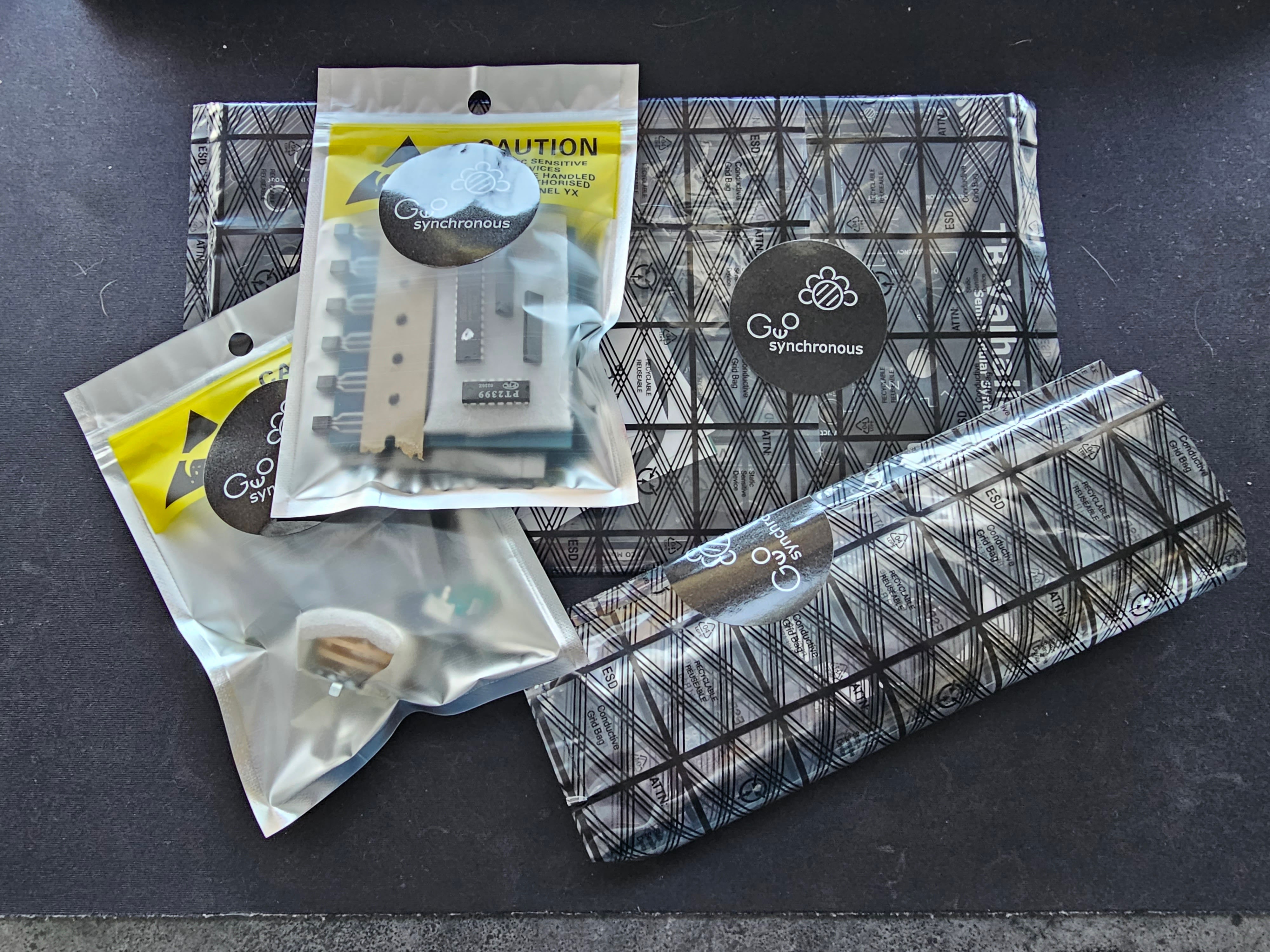
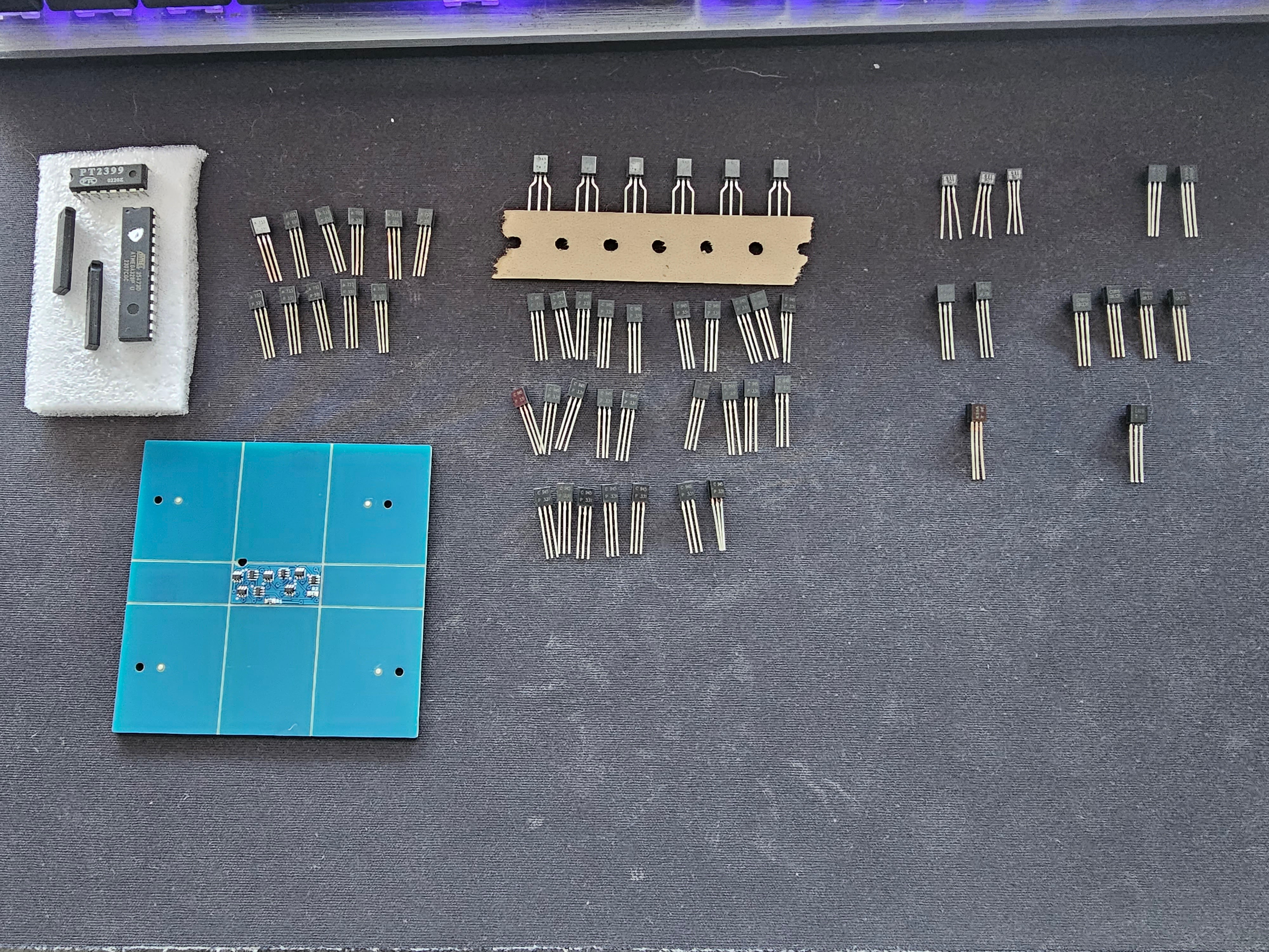
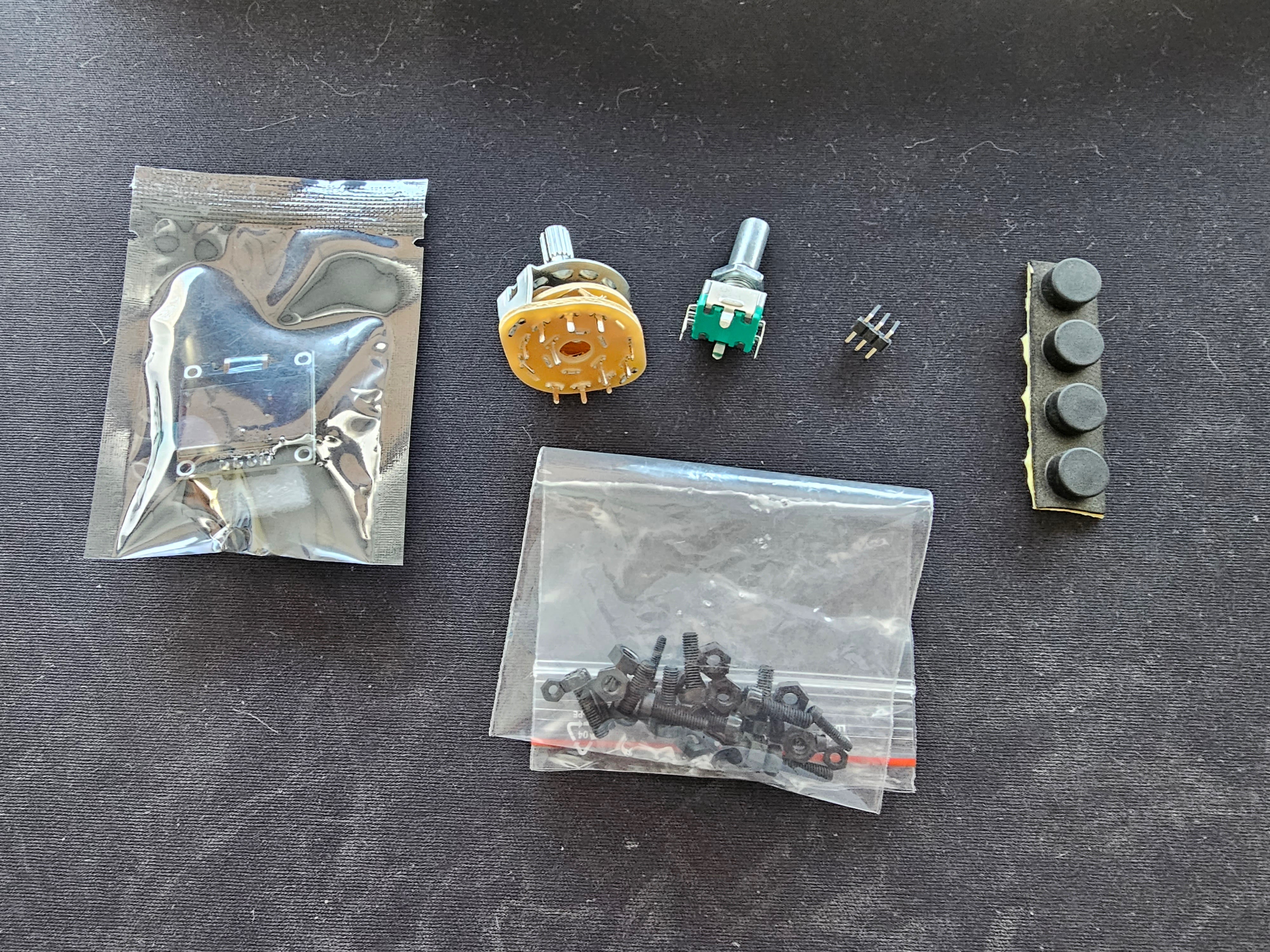
Partial Kit
PCB & Panel and includes “rare” parts.
- All PCB & Panel
- Includes rare parts marked in green in the BOM.
Fully Built
Built and Calibrated
- Limited supply
- Fully built, tested and calibrated module using quality components and NOS rare parts.
- Each TB-Valhalla is built to order – expect ~2week build time from ordering point.
- PRICES ARE IN NZD!

You must be logged in to post a comment.